
PeterL
New member
As others have noted, the "power outlet" Yamaha saw fit to install on the Tracer GT is fused for only 2 amps, insufficient to reliably run even a small compressor to top up your tires. This is totally inconceivable to moi, especially on a motorcycle with touring pretensions. Dunno about you, but I check my tires every morning, and I don't always wake up within easy reach of a gas station, or even a non-pit toilet. Self-sufficiency makes life SO much easier!
I decided to make just a *few* alterations:
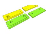
Next up, most who contemplate doing this would likely just zip-tie the relay in place and call it good. Not me. I was compelled to spend a couple of days modeling a relay-mount in CAD, running it through my 3d printer, making alterations, print again, and so on. After a few go-rounds, I cheerfully emerged from my lair with a two-plate system that clamps securely about the metal windshield/dash support and which lets me bolt the relay -bracket- firmly in place, allowing for easy swapping of the relay itself if it ever fails, without bothering the wiring in the least. (retired engineer here, I _always_ try to anticipate failures and ease repair time and effort [mine]) FWIW, the concept is to minimise impact shock from an unsecured mass bouncing around. This way, whilst you get the unavoidable vibration any vehicular component is subject to, the relay is securely held to the metal support structure and cannot gyrate around and damage either itself or the insulation on live wiring.
The takeoff from the battery was via two rIng terminals, through a weatherproof ATC fuse holder, left conveniently resting directly atop the battery for ease of access. 14AWG cabling was run under the plastics and terminated behind the dash with the relay itself.
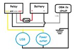
Once the hardware bits were in place, time to do up the wiring (standard 12v 4-pole relay spec):
For anyone who might care to make use of it- I've posted the STL files for the bracket pieces on Thingiverse.com, along with assembly instructions here.
Ride safe y'all!
I decided to make just a *few* alterations:
- Turn the 2a feed into a trigger for a power relay, this drawing up to 30a max direct from the battery via a fused cable
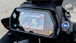
- install a weatherproof heavy-duty power outlet in place of Yamaha's lightweight unit
- install a dual USB QC 3.0 outlet (also weatherproof) on the opposite side of the dash. This is backwards compatible for older devices, but it will fast-charge a current-gen smartphone in a fraction of the time a standard 2a feed would take.
Next up, most who contemplate doing this would likely just zip-tie the relay in place and call it good. Not me. I was compelled to spend a couple of days modeling a relay-mount in CAD, running it through my 3d printer, making alterations, print again, and so on. After a few go-rounds, I cheerfully emerged from my lair with a two-plate system that clamps securely about the metal windshield/dash support and which lets me bolt the relay -bracket- firmly in place, allowing for easy swapping of the relay itself if it ever fails, without bothering the wiring in the least. (retired engineer here, I _always_ try to anticipate failures and ease repair time and effort [mine]) FWIW, the concept is to minimise impact shock from an unsecured mass bouncing around. This way, whilst you get the unavoidable vibration any vehicular component is subject to, the relay is securely held to the metal support structure and cannot gyrate around and damage either itself or the insulation on live wiring.
The takeoff from the battery was via two rIng terminals, through a weatherproof ATC fuse holder, left conveniently resting directly atop the battery for ease of access. 14AWG cabling was run under the plastics and terminated behind the dash with the relay itself.
Once the hardware bits were in place, time to do up the wiring (standard 12v 4-pole relay spec):
- post# 85 connects to -12v (NEGATIVE) from the vehicle battery
- post# 86 connects to the POSITIVE lead from the old power outlet feed. This is your trigger, so the outlets will only be live when the key is ON.
- post# 87 connects to +12v (POSITIVE) from the vehicle battery
- post# 30 feeds +12v to both the power (formerly 'cigarette') receptacle and USB outlets. Yes this gives a common point of failure to both, but the alternative of doing two separate relays just did not seem worth the bother at this point. Relay failures are rare, and I am only running this at 2/3 capacity max (rated and wired for 30a, fused for 20).
For anyone who might care to make use of it- I've posted the STL files for the bracket pieces on Thingiverse.com, along with assembly instructions here.
Ride safe y'all!
Attachments
-
 46.5 KB Views: 4
 -
 386.3 KB Views: 4
 -
 394.3 KB Views: 4
 -
 122.7 KB Views: 4